THE
HISTORY OF TID TUGS
This
website aims to bring together all available information and
photographs concerning TID class tugs. If you have more information,
stories, pictures, experience of working on TID tugs or can
correct anything within the website, please contact
Martin Stevens.
The
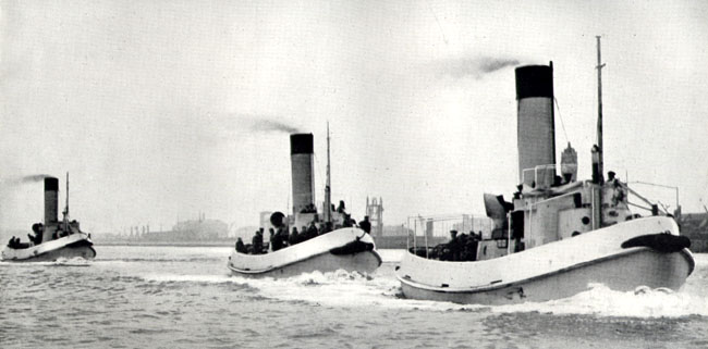
TID Story - "One Tug Per Week"
|
In
1943 the Ministry of War Transport decided to introduce a new class
of tug. Urgent demands were made for small tugs for harbour and dock
work, and to support the impending invasion preparations. The terse
statement made to satisfy the needs was simple:
"Design, organise and start
work immediately toward achieving, in the shortest possible time,
the delivery of one tug per week, using in the process, little or
no shipyard labour."
Constructional engineering yards were already hard-pressed and could
not accept orders for tugs, generally launched from conventional slipways.
However, there was more capacity in manufacturing establishments for
welded work rather than riveted work. For instance, railway train
manufacturers were not in demand so perhaps they could be used for
producing these tugs. It was evident that the planning must allow
for work to be placed with a number of different firms, and the basic
design for an all-welded tug emerged.
|
Technical
Innovation
Pre-fabricated
construction in shipbuilding had risen to huge proportions
in the United States but there was little, if any, in Britain.
Now, however, its possibilities were investigated, with a
tank-tested model requiring only minor modifications before
acceptance.
The
result was a complete departure from normal British shipbuilding
practice, in shape, in design detail and in the construction
of pre-fabricated parts for the assembly of a vessel - welded,
not riveted. It was an advance in technical and industrial
development.
So
came the "TID" tug. It was to be mass-produced and
of straight-line form. The hull was designed on the 'hard
chine' principle, all design lines of the same strake of plate
being parallel, giving frames in straight lengths. There were
to be no bent frames, and curvature in the shell would apply
in one direction only, i.e., with no twist in the plates.
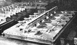
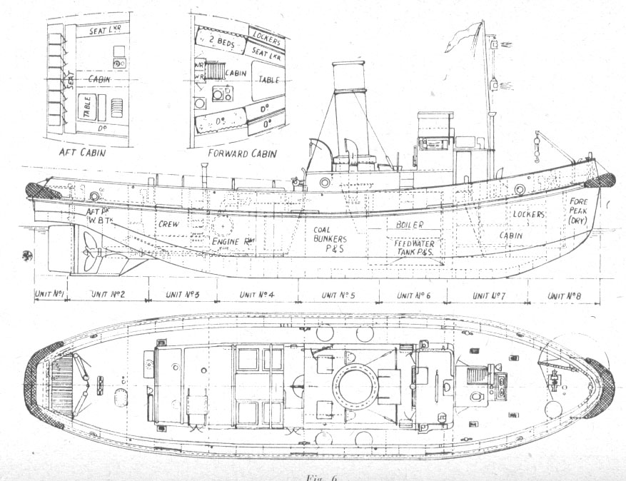
The
design was subdivided to eight units, cut right across the
vessel, with all joints of units arranged to come midway between
two frames. There were independent drawings for each unit,
with the unit sizes restricted to maximums of 10 ft length,
17 ft width, 13 ft depth and a weight of six tons for transport
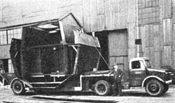
by road, sometimes up to distances of 200 miles.
|
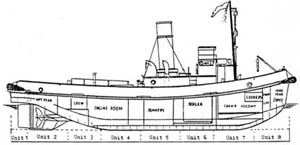
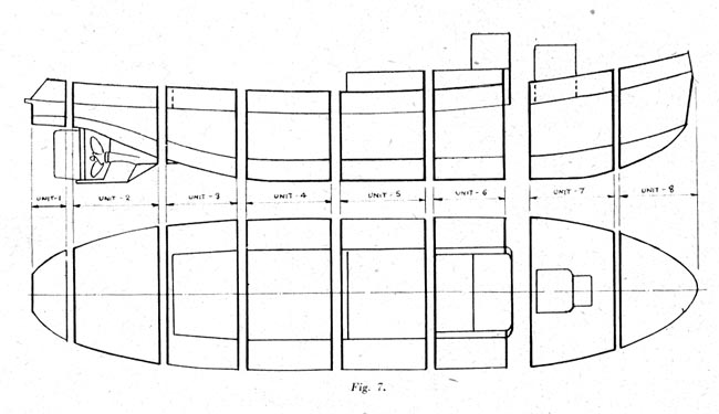
The
eight sections of the TID
|
|
click
drawing for general arrangement plan
|
Contractors
Initially,
contracts for making the units were awarded to
William Neill Ltd.
Foster Yates and Thom,
R.Dempster and Sons,
Charles Roberts and Co. Ltd.,
Newton Chambers and Co. Ltd.
The original order was for twelve tugs to be constructed,
but when this was increased to fifty, Dunstons allocated the
work so that two companies were responsible for making each
section. This meant that supplies were assured if enemy bombing
put one company out of business.
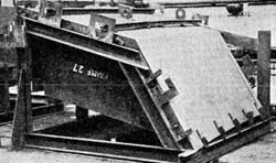
Unit
One, the stern, a 4ft 2" section was made by
Robert Jenkins and Co., also Foster Yates and Thom.
Unit Two, the aft peak tank, 10 ft, was made
by A.J.Riley and Son, also Foster Yates and Thom.
Unit Three, the after cabin, 8ft 4",
was made by Nortons Tividale Ltd., also Robert Dempster and
Sons.
Unit Four, the engine room, 10ft., was made
by Wrights Forge and Engineering Co., also Robert Dempster
& Son. It is known that with such a prefabricated system,
the bedding of the engine and alignment of the propeller shaft
were difficult, and Robert Dempster and Son were trusted with
this area from the outset.
Unit Five, boiler room and bunkers, another
10ft. section, was made by John Booth and Sons (Bolton), also
Newton Chambers and Co. Ltd..
Unit Six, boiler room and bridge, 8ft 4",
was made by Head Wrightson and Co., also Charles Roberts and
Co. Ltd..
Unit Seven, forward cabin, a 10ft section,
was made by C. and W. Walker Ltd., also William Neill and
Sons.
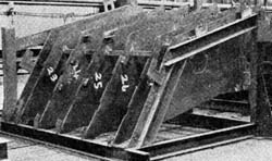
Unit Eight, the bow section (incorporating
the chain locker and fore peak), a 9ft 2" unit, involved
the most difficult shaping, It was made by Orthostyle Ltd.,
also William Neill and Sons.
|
|
Welded
by Women
The longitudinal seams of plates were left unwelded for a length of
10 inches at either side of a joint, in order that the plates might
be 'sprung' together if any slight deviation from the correct dimension
occurred. Each separate unit was completed with many of its fittings
in position: a special feature of the after-most unit being that it
was completed with the rudder, propeller and tailshaft in place.
At fitting-out
stage - after completion and launch of the hull - the engine bedplate
chocks were machined to dimensions taken from the engine after it
had been packed and wedged up in alignment with the tailshaft.
The
White TID - from a promotional brochure
However, with some fittings - namely engine room valves, pipework
and auxiliaries - it was deemed unwise to have these fitted to the
units by the sub-contractors, due to possible movement by vibration
during transit. Therefore, such items were fitted at the shipyard,
prior to the transverse all-round welding which turned eight separate
units into a complete tug. Many women welders were involved in the
construction of TIDs. At the end of the war, after pressure from the
Trade Unions, they were all sacked.
|
Made
in Thorne, Hessle, and Sunderland
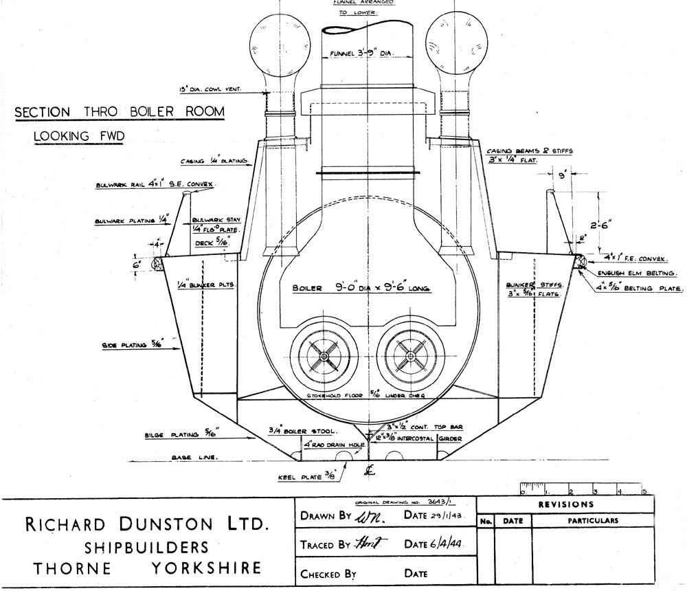
Hull measurements of the tug were 65 ft length (bp), 74 ft
(oa), 17 ft breadth and 8 ft depth, giving 54 gross tons.
The draught was 7.3 ft with bunkers and water tank full. Full
displacement was 124 tons, bollard pull two tons and full
bunker capacity eight tons (coal) or nine tons (oil).
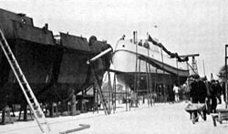
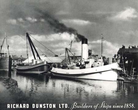
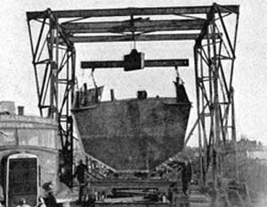
Assembly
of the hull was done by
Richard Dunston Ltd., at their Thorne shipyard, (who later
took over Henry Scarr Ltd. of Hessle), in Yorkshire and late
in the programme, to keep up with demand, by William Pickersgill
& Sons Ltd., at Southwick, Sunderland.
A
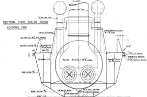
hull was put together every five days - the record was four.
The boiler, the two-cylinder compound engine, which developed
220 indicated horse power, and superstructure were fitted
after the launching. For this purpose, units Nos. 4, 5 and
6 had their upper casings merely tack-welded into position
by the contractors. These were removed by cutting the tacks
and were easily replaced afterwards.
|
click
drawing for larger version |
|
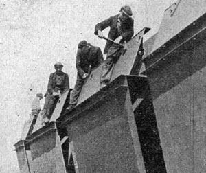
'Springing'
the section joins prior to welding
|
TID
Relay
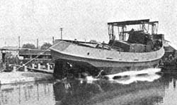
At
Dunston's, the first TID was towed from Thorne to Hessle,
her engine and boiler were fitted, ran trials back to Thorne
and as she left for delivery towed the next completed hull
downstream for its machinery installation. This went on week
after week, each completed TID towing the next one.
During
the four years of TID building, their appearance changed little,
only minor changes to the deckhouse, boiler room and accommodation
being made, most of these on the Sunderland-built craft. All
TID's were built with an open bridge, so subsequent enclosed
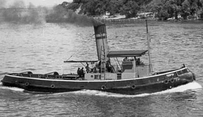
wheelhouses tended to be of individual designs.
The initial order from the Ministry of War Transport for twelve
TID tugs quickly became twenty five; then, as production began,
was altered to fifty, and as work quickly progressed the figure
was doubled to 100. All were ordered as coal burners, to give
7-8 knots and with the liberation of Europe in mind, the main
intention was for their use in smaller ports and anchorages.
|
|
TIDs
Abroad
Then
came the likelihood of the use of TID tugs in the Mediterranean
and the Far East and another fifty were ordered. It was necessary
to modify the design to make them burn oil. This was due to
the lack of coal - or its generally poor quality - at prospective
bases, and to give increased range to the vessels.
TID 132 on service in the Far East
Such conversion, including lowering funnels, required only
slight structural modifications to two of the eight prefabricated
units. At the same time it was decided to convert similarly
the second batch of fifty tugs ordered, but with these already
in production it was found possible to change only ten of
them to oil. Finally, a group of thirty two oil-burners for
tropical service was built, with generators to operate a boiler
room ventilator fan and electric lights, and equipped with
canvas awnings.
|
|
|
|